Зарегистрируйтесь сейчас для лучшей персонализированной цитаты!


Network administrators have to deal with a lot of things every day, not only to keep the network stable, but also to ensure that the computer works properly. These daily network management and maintenance is also skillful, when computer hardware problems occur after the most commonly used method is the replacement method, take another computer of the same parts to replace the suspected damaged parts. We can also use this method to solve network problems.
For example, if we encounter a broadcast storm on the internal network due to poor network planning, the replacement method is the only way to solve the problem. We can unplug all the terminals from the switch or router one by one and add them to the network one by one. It's a dumb way to do it, but it's often the most useful and takes the least amount of time. Now for you to analyze one by one, why is said to be fast it, these are the usual preparation work to be done.
Small ways to reduce operating time
1. Usually the models of spare parts switch box unpacked (box intact retained in the warehouse(1), ear mounted.
2. Each floor to put a good person ladder, to save the fault when looking around for the ladder time.
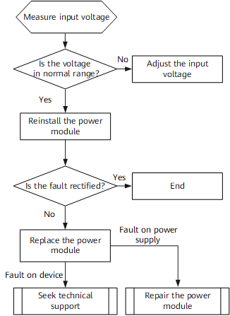
3. First determine the faulty equipment rack position, whether the indicator light is on.
4. If not, the rack position is correct. Immediately introduce utility power, recharge the equipment with utility power and test whether the equipment is faulty.
5. If it can be started normally, then ask the faulty applicant. (At this point, it is judged that there may be a problem with the power cord, or the switch may not be quite normal)
6. If it can not start normally, then enter the replacement session.
The faulty equipment is removed and installed on, and since there will be switches in use by the business in the immediate vicinity, this session cannot be time compressed. Care must be taken in this session to ensure that non-faulty equipment is not affected.
The replacement session is detailed in more detail below.
If an operating switch or router unfortunately fails to power up at all, we have to replace it with a spare switch of the same model to take over.
First we pick up the switch and power it up in a non-business operating environment to ensure that the new switch can communicate normally with our PC computers.
The magic five steps:
1, is the switch and debugging PC connection
2, is the configuration file renamed to config.cfg
3, is uploaded config.cfg
4, is removed from the faulty device
5, is to install and configure the new device and shelves
01 Tools and PC settings
Here it is recommended to power up and configure the switch in a non-business environment to avoid unnecessary impact on normal business.
Here we press the switch is not any configuration of the switch setup physical connection switch control port and network card switch power on, we will switch the CONSOLE cable to the switch end of the CONSOLE port, find a direct connection to the network cable, the debugging of our PC and the switch is connected, as long as you can communicate with the switch on the line.
Then the other end, we can not be connected to their own debugging PC it, if not the same interface, we have to use the USB to Oh, remember to install the usb to serial port driver (find it on the Internet), so that this line can work.
After the driver is installed, we will set the rate, my computer right-click is not out of the management of this option ah ah ah, then we choose to manage, and then it is to choose as shown in the figure of Oh. Finally point OK.
So the physical connection is complete.
02 PC IP settings
Select Online Neighborhood Right-click, then it is selected local connection right-click and select Properties, this time out of the local connection properties dialog box, we set up according to the following chart on the line.
Finally remember to click OK. Remember to connect the network cable to the electrical port of the switch.
03 Connect to the switch with secureCRT
Before proceeding to the next cycle, it is necessary to restore the network to the state it was in before the last program was implemented. Keeping the changes to the network from the previous scenario will likely lead to new problems.
Cyclic troubleshooting can have two entry points:
When a troubleshooting scheme for one possible cause does not achieve the desired purpose, loop into the next possible cause to develop a troubleshooting scheme and implement it;
When the troubleshooting plan for all the possible causes list fails to achieve the purpose of troubleshooting, reproduce the fault-related information collection to analyze the new possible causes.
Here to the tool secureCRT as an example, you can download the Chinese version of the crack on the Internet, after installation. Open the already installed secureCRT, click the Quick Connect item, the second icon in the following figure, and then select the protocol, port, baud rate of the Quick Connect according to the following figure, and then point to connect, you can connect to the switch.
04 FTP server tool installation
FTP tool we choose 3COM3CDaemon2.0 Chinese free installation version, open the tool as shown in the following chart settings, click on the FTP server, we choose the pop-up dialog box we choose to then set the user name and password, the user directory, and then click to save the user, and then finally point OK. So our FTP server is good, remember to debug the IP of the PC is the FTP server access IP.
Next we connect to the switch and setup:
05 Install and configure the new device and rack
1. Switch-side setup
We have just used the tool secureCRT to connect to the switch using the Serial protocol. Engage a carriage return and this is the command line management interface will appear.
1) Set the IP of management VLAN
For the convenience of setting, we use the default VLAN 1 as the management VLAN here, the default management VLAN of the switch is VLAN 1.
Enter management VLAN 1
[H3C]interface Vlan-interface 1
Set the management IP to 192.168.1.101.
[H3C-Vlan-interface1]ip add 192.168.1.101 255.255.255.0
Since all ports belong to VLAN 1 by default, we don't need to change the rest.
At this point, we ping the switch on the debug PC to see if we can get through.
This will be OK.
Save the configuration (only by saving the configuration, we can validate the subsequent operations)
Note: If the uploaded configuration can not take effect, here to restart the device!
2) On the PC, copy the complete script of the switch to the user directory of the FTP server and rename it as config.cfg.
3) Connect to the FTP server
ftp 192.168.1.110
Then we will be asked to enter the FTP user name and password, which we just set in the 3COM3CDaemon2.0 Chinese free installation version to lose on the line.
4) Enter FTP to start the previous backup configuration file uploaded to the switch, here the file name must be changed to config.cfg at the same time remember to complete the suffix. [ftp]get config.cfg
5) If the upload is normal, you can see that the file size of the uploaded file is the same as the file size in our FTP directory.
Once the transfer is complete, we need to quit FTP
[ftp]quit
6) Reboot the device(remember here if there is a prompt whether to save the existing configuration, we choose N)
2. Verify the configuration
It is necessary to verify the validity of the configuration for the new device. After rebooting the device, enter the switch to check whether the configuration is consistent with the original script.
You can use the file comparison tool to compare.
1) File comparison method:
2) After the configuration is completed, tap the File option in the point, drop down and tap Record Session to come out a dialog box, select the corresponding path and file name, and then tap Save.
3) In the configuration interface on the switch, enter dis cur and keep pressing the space bar; until there is no content output. At this point we disconnect from the control port of the switch.
4) Use the file comparison tool to compare the file we just saved (Example 123) with the configuration script we backed up before. If there is no discrepancy, it will be OK.
3. Physical location change
1) We must make a good mark or mark, which cable, fiber is plugged into which port.
2) Disconnect the power and ground cables of the failed device;
3) Unplug all the network cables and optical fibers of the faulty equipment;
4) Loosen the fixing screws of the faulty equipment and remove the faulty equipment;
5) Install the new device, the order is the reverse of the order of removing the faulty device, first fixing screws, then connecting the network cable and fiber optic, and finally connecting the power and ground cables.
Friendly reminder, never pay attention, this fourth point of the five steps should be especially careful, shall not touch the power cord, network cable, fiber optic of other equipment. Avoid causing more damage.
In this way our express replacement of faulty equipment is completed.
►►►
Troubleshooting process documentation
Troubleshooting process documentation mainly includes the following aspects:
► Description of fault phenomenon and related information collected
► Network topology drawing
► List of devices and media used in the network.
► List of protocols and applications used in the network.
► Possible causes of the failure
► Solutions and implementation results for each possible cause
► The experience of the troubleshooting.
Other: e.g. list of references used in troubleshooting, etc.
Summary
Being able to properly maintain a network as trouble-free as possible, and ensuring that when a failure occurs, the problem can be quickly and accurately localized and troubleshooted, is a challenge for network maintenance and management personnel.
This requires not only an in-depth understanding of network protocols and technologies, but also, more importantly, a systematic approach to troubleshooting ideas and their judicious application to isolate, decompose, or reduce the scope of troubleshooting a complex problem in order to fix network failures in a timely manner.
For network product list and quote, please visit: https://www.hi-network.com/categories/cisco or contact us at www.hi-network.com (Email: [email protected])
 Горячие метки:
Huawei переключается
В сети интернет
Горячие метки:
Huawei переключается
В сети интернет
Зарегистрируйтесь по электронной почте сейчас для еженедельной акции акции
100% free, Unsubscribe any time!
Add 1: Room 605 6/F FA YUEN Commercial Building, 75-77 FA YUEN Street, Mongkok KL, HongKong Add 2: Room 405, Building E, MeiDu Building, Gong Shu District, Hangzhou City, Zhejiang Province, China
Whatsapp/ тел: +8618057156223 * телефон: *: 0086 571 86729517 Tel in HK: 00852 66181601
Электронная почта: [email protected]
 English
 Pусский
 Français
 Español
 Português